Difference between revisions of "Measurement of power"
| Line 6: | Line 6: | ||
Power measurements are made relative to a certain position in an electrical network. The location where a measurement is made is often different to where a power model is valid, and a conversion between the power relative to the two locations in the network is needed. |
Power measurements are made relative to a certain position in an electrical network. The location where a measurement is made is often different to where a power model is valid, and a conversion between the power relative to the two locations in the network is needed. |
||
| + | |||
| + | The software considers two efficiency factors when performing the conversion, one mechanical efficiency and one electrical efficiency. |
||
| + | |||
| + | * The '''mechanical efficiency''' is the drive efficiency from the motor output shaft to the mill shell and includes the pinion losses and any gearboxes. (gearless: the motor output is at the mill shell, so this efficiency is always "1.0"). The efficiency is expressed as a decimal, so a pinion gear with 98.5% efficiency is expressed as 0.985. |
||
| + | |||
| + | * The '''electrical efficiency''' is the efficiency measured from the DCS measurement position to the motor output shaft and includes the motor efficiency (which you can read from the name-plate) and possibly drive system and conductor losses. Many mines read the electrical power at the motor leads so the electrical efficiency is just the motor losses. Note that some modern drive systems (e.g. ABB ACS6000 and any gearless drive) will provide the control system with the motor's output power corrected to be mechanical. For these systems (especially gearless), set the electrical efficiency to 1.0; otherwise express the effienciency as a decimal (e.g. 0.96 for 96%). |
||
===Power at the Mill Shell=== |
===Power at the Mill Shell=== |
||
Latest revision as of 17:24, 20 April 2026
Measurement of power

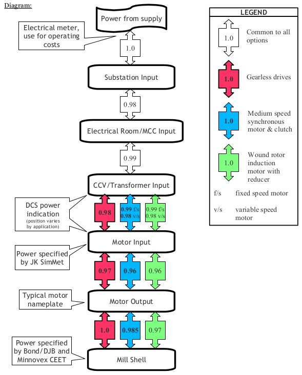
Each piece of an electrical network introduces electrical loses such as voltage drop (resistance and heat) and alternating current phase misalignment (power factor). Mechanical loses occur between a motor output shaft and driven equipment, such as heat losses in gearboxes and pinion gears. Because of these cumulative power losses, the actual amount of power declines as it travels through an electrical and/or mechanical network.
Power measurements are made relative to a certain position in an electrical network. The location where a measurement is made is often different to where a power model is valid, and a conversion between the power relative to the two locations in the network is needed.
The software considers two efficiency factors when performing the conversion, one mechanical efficiency and one electrical efficiency.
- The mechanical efficiency is the drive efficiency from the motor output shaft to the mill shell and includes the pinion losses and any gearboxes. (gearless: the motor output is at the mill shell, so this efficiency is always "1.0"). The efficiency is expressed as a decimal, so a pinion gear with 98.5% efficiency is expressed as 0.985.
- The electrical efficiency is the efficiency measured from the DCS measurement position to the motor output shaft and includes the motor efficiency (which you can read from the name-plate) and possibly drive system and conductor losses. Many mines read the electrical power at the motor leads so the electrical efficiency is just the motor losses. Note that some modern drive systems (e.g. ABB ACS6000 and any gearless drive) will provide the control system with the motor's output power corrected to be mechanical. For these systems (especially gearless), set the electrical efficiency to 1.0; otherwise express the effienciency as a decimal (e.g. 0.96 for 96%).
Power at the Mill Shell
Power models in SAGMILLING.COM are all expressed relative to the mill shell for both specific energy consumption (eg. Esag, kWh/t) and for mill power draw models (eg. Nordberg ball mill power prediction for a mill geometry). This relative to the mill shell definition roughly corresponds to the amount of energy that ore consumes given an efficient set of mill bearings, liners, etc.
Power at the DCS
A Distributed Control System (DCS) consists of a set of sensors in the plant that send information back to a central processing computer that turns the sensor information into actual measurements. For example, given a single-pinion synchronous motor system where:
- A voltage sensor sits on the medium voltage bus feeding the LCI unit in the motor drive.
- A current sensor in the MCC panel is connected to the LCI output ahead of the conductor leading to the motor input.
- These two measurements are combined in the DCS computer resulting in a power measurement relative to "somewhere in the network". There is a voltage loss in the LCI (so the voltage can only be relative to LCI input), but the current will be similar at the LCI input and output. Therefore, the combination of Volts & Amps in the computer actually corresponds to the measurement of power at the LCI input (corresponds to the input to the CCV position on the diagram as LCI is an alternative technology that does the same overall job).
Calculating the Conversion
Losses of power are combined by multiplication.
Continuing the example above, if the DCS indicates a 5100 kW power, the corresponding power at the mill shell would be calculated as follows:
- The electrical system for a synchronous motor with pinion corresponds to the blue set of values on the diagram.
- The LCI input corresponds to the "CCV/Transformer Input" block on the diagram. The LCI does the same job as a CCV (cycloconverter); they are different technologies to achieve variable speed in synchronous motors.
- The losses for a variable speed drive between the "CCV/Transformer Input" block and the "Motor Input" block is 0.98.
- The losses for synchronous motor "Motor Input" block and "Motor Output" block is 0.96.
- The losses for a medium-speed pinion (no gearbox) "Motor Output" block and the "Mill Shell" block is 0.985.
- The total losses is calculated as 0.980 × 0.960 × 0.985 = 0.927.
- The power at the mill shell (the pinion output) is 5100 kW × 0.927 = 4726 kW.
- The missing 374 kW are lost to heat in the electrical network and the gears, and a little bit to the power factor of the system.
Warning: This approach generally neglects significant power factor loses. If a mill drive system is being used for power factor correction at the minesite, then a site-specific network diagram with the actual loses including power factor must be created.