Benchmarking: Bond - Boddington
Contents
Benchmarking: Bond/Rowland SSBM model - Boddington HPGR circuit
Sources, SAG 2011 conference
Steven Hart, S., Parker, B., Rees, T., Manesh, A. and McGaffin, I. COMMISSIONING AND RAMP UP OF THE HPGR CIRCUIT AT NEWMONT BODDINGTON GOLD, SAG 2011 paper number 41.
Hart, S., Rees T., Tavani, S., Valery W. and Jankovic, A. PROCESS INTEGRATION AND OPTIMISATION OF THE BODDINGTON HPGR CIRCUIT, SAG 2011 paper number 126
- Primary crusher product (model F80) approximately 160 mm
- Secondary crushing circuit 4×MP1000 crushers, typically using about 60% of power draw
- Tertiary crushing circuit 4×2.4 m by 1.65 m HPGR, each with two 2.8 MW drives
- Fine screen aperture 10 mm
- Ball mill 26 ft diam by 44 ft long with twin-pinion 8 MW drives
Plant survey conducted April 2010. Ore sample was sent to local laboratory (assumed to be ALS Ammtec) gave following determinations:
- UCS 135 MPa
- WiC 27.7 (metric)
- WiRM 20.0 (metric)
- WiBM 14.4 (metric)
- DWi 9.3; A×b 30
- Bond Ai 0.52
Plant operating parameters:
- primary crusher product (circuit F80) = 160 mm
- secondary crusher specific energy consumption 0.5 kWh/t with product size 38 mm
- power draw of secondary crushers = 460 + 554 + 583 + 581 = 2178 kW, assumed to be at motor input
- secondary crushing throughput 4560 t/h; not clear if this is fresh feed or includes a circulating load.
- throughput 1100 t/h per grinding line × 4 lines = 4400 t/h
- HPGR specific energy consumption, EHPGR = 1.40 kWh/t
- overall Ecrush = 1.90 kWh/t
- HPGR circuit product size (T80) 6 mm
- ball mills drawing about 14 MW (assumed DCS, works out to 13.0 MW at mill shell)
- Eball = 13000 kW / 1100 t/h = 11.82 kWh/t (at shell)
- circuit P80 ranged from 92 to 128 µm (use 100 µm)
Sources, other
AGC AusGroup project fact sheet. Photo of the ball mill bay indicates:
- Mills are trunnion mounted. Simulate with Nordberg wet overflow model.
- Motors are induction, use 0.96 as motor efficiency.
- Mechanical drives include gearboxes, use 0.97 motor efficiency to shell.
- mill shell is 44.5 ft long (F:F), use 44.0 ft EGL
Modelling
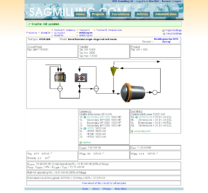
Use the Bond/Rowland single stage ball mill circuit model with the HPGR-BM flowsheet.
Ball mill model:
- Use the Nordberg wet overflow ball mill model
- Quantity 4
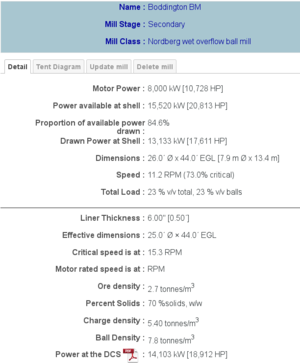
- Mill dimensions, diameter 26 ft, EGL 44 ft
- motor mechanical efficiency 0.97; motor efficiency to DCS 0.96
- Assume 6 inch liner thickness, 7.80 t/m3 ball density.
- To achieve 14 MW at DCS, assume speed is 73% of critical and load is 23 % v/v (mills are fixed speed, unable to find speed in literature; load is low, but probably kept low due to problems getting throughput in HPGR circuit).
Secondary crusher model:
- Quantity 4.
- MP 1000 crushers, use 1000 HP motor.
- set mechanical efficiency to 0.60.
- contribute Esecondary of 0.50 kWh/t to Ecrush
HPGR model:
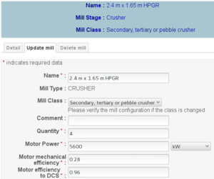
- Quantity 4.
- HPGR motor 5600 kW (actually 2 × 2800 kW)
- Adjust the mechanical efficiency to get Ecrush of 1.9 kWh/t (EHPGR of 1.4 kWh/t),
- results is mechanical efficiency of 0.30.
Bond/Rowland SSBM Circuit model:
- Set the crusher product size to 6000 µm
- Circuit feed size 160 000 µm and product size 100 µm
- Adjust the Essbm calibration factor to get Eball of 11.8
- set Essbm calibration factor to (-0.13)
- Gives a throughput of 4400 t/h.
- gives 5% reduction in ball mill operating work index (13.6) versus laboratory Wi (14.4).
- Result is 4431 t/h circuit throughput with Etotal of 13.78 kWh/t (close enough)
Discussion
Essbm calibration factor versus Etotal displayed
The Essbm calibration factor in the Bond/Rowland SSBM Circuit Model is not the same as the "-19%" displayed on the "Etotal" line of the flowsheet. The calibration factor that is input in the circuit settings relates to a hypothetical "perfect" cone-crushing circuit with slightly different inter-stage transfer sizes than is simulated in the actual circuit.
The "Etotal: Essbm" factor shown at the bottom of the flowsheet refers to the actual Etotal of this simulated flowsheet (Esecondary + EHPGR + Eball) versus the hypothetical "perfect" cone-crusher SSBM circuit described by Rowland.
Microcracking/phantom cyclone/ball mill performance
The particle size distribution out of an HPGR is not "Bond-compatible" and the extra fines result in a phantom cyclone effect similar to a SAG mill. Moreover, there are reports of additional cracking within the matrix of the rock (microcracking), but that effect is probably similar to the phantom cyclone effect for modelling purposes. The reported reduction in ball mill operating work index due to these effects is in the range of 5% to 10% versus a laboratory ball mill work index determination. The predicted 5% reduction in WiO fits nicely with the literature.
Secondary crushers, operating work index
The Bond (impact) crushing work index is given as 27.7 based on a laboratory determination. Use the circuit survey data to compare the operating work index to this laboratory determination.
The reported power draws of these MP 1000 crushers were 460+554+583+581 for a total of 2178 kW at the DCS. Use a conversion 0.96 for DCS to "shell" power gives 2090 kW. The secondary crushers are reported to process a 160 mm primary crushed feed into a 38 mm secondary crushed product. Back-calculating the operating work index of the crusher gives:

Solving for WiO gives 18.1 kWh/tonne (versus laboratory determination 27.7 kWh/t).


